A 5-Step Guide to Build a Pseudo-LiDAR using Stereo Vision
If you've been adventuring yourself in the shallow waters of 3D Computer Vision, you probable came across a term some engineers use: "Pseudo-LiDAR". It's a term Tesla made popular, but that many other companies in the self-driving car space use commonly to refer to 3D Computer Vision.
In a recent blog post, I describe the field of 3D Computer Vision, and I show how many 2D algorithms are powerless and practically useless in autonomous driving. Object detection algorithms such as YOLO or RetinaNet may return 2D Bounding Boxes giving the obstacles’ positions in an image, but these 2D algorithms do not deal with 3D. They do not return the distances of each obstacle, nor their orientation, or real shape. It's just flat bounding boxes!
To return the distance of an obstacle, robotics and self-driving car engineers use another sensor named LiDAR (Light Detection And Ranging) that uses lasers to generate a point cloud and return the depth information. The more robust approaches also use Sensor Fusion to combine the data from camera and LiDARs.
But this approach requires the use of a LiDAR, which can be very costly, and could, according to Elon Musk "doom" a company.
In this article, we'll do an in-depth exploration of the alternatives companies like Tesla or Mobileye use to solve the point cloud reconstruction and more generally the depth estimation problem by building what's called a Pseudo-LiDAR.
So let's begin:
What's a Pseudo-LiDAR? Point Clouds Estimation in 5 Steps!
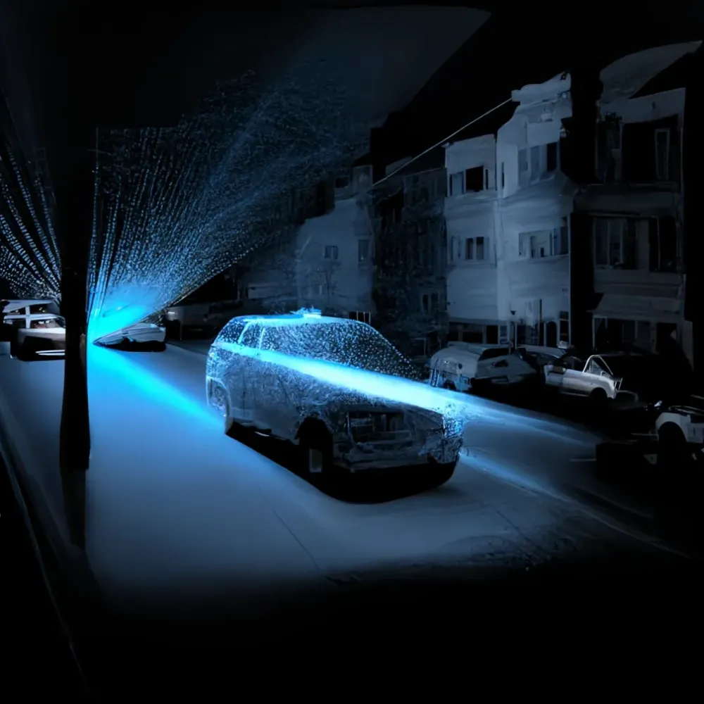
A "Pseudo-LiDAR" is the term we use when we want to recreate a point cloud from cameras only. What's a Point Cloud? It's what's obtained by LiDARs (Light Detection And Ranging) systems:
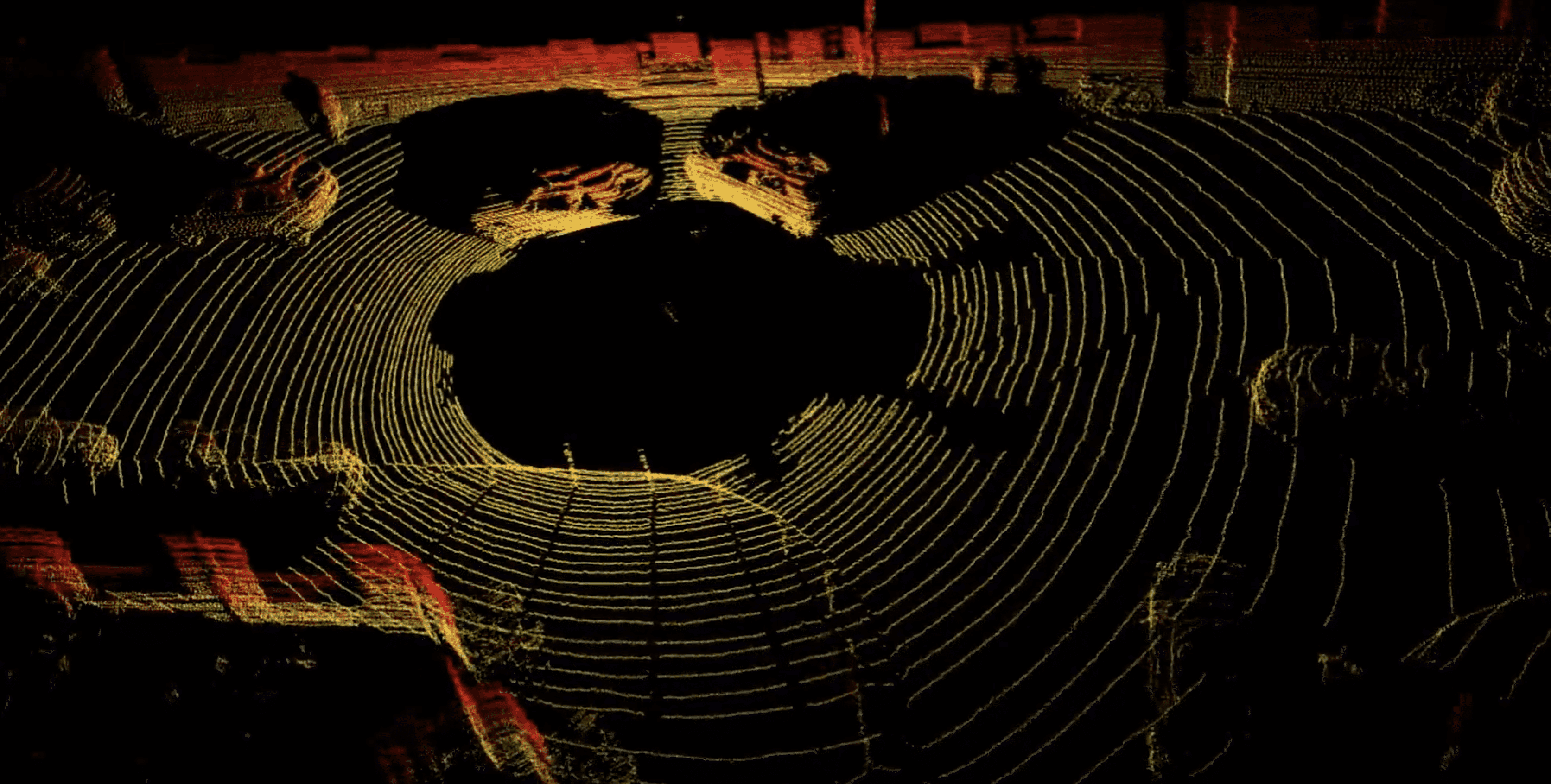
We are working in a 3D World, and each point has an XYZ position. In most recent LiDARs, such as FMCW LiDARs, each point also has a velocity. From there, we can do many things, such as 3D Object detection, 3D Object Tracking, or plain Depth Estimation.
So let's begin with an important claim:
To build a Pseudo-LiDAR, you should use at least 2 cameras.
It's not mandatory, and many research papers try to solve it using just a monocular camera, but Stereo Vision is the way to go. When one camera only provides a 2D view, two cameras can help us "triangulate" the position of each pixel, and thus rebuild this 3D Map.
From 2 cameras, we can retrieve the distance of an object. This is the principle of triangulation, and this is the core geometry behind Stereo Vision. Here's how it works:
- Stereo Calibration - Retrieve the key parameters from the cameras
- Epipolar Geometry - Define the 3D Geometry of our Setup
- Disparity Map - Compute the Disparity Map
- Depth Map — Build a Depth Map from the Disparity Map
- 3D Reconstruction — Build a Pseudo-LiDAR by combining the Depth Map obtained in (4) and the Camera Parameters obtained in (1)
Looks straightforward, let's begin:
Step 1 — Why Stereo Calibration Matters
When looking at any image on the internet, it's likely that the camera has been calibrated. Every camera needs calibration. Calibration means converting a 3D point (in the world) with [X,Y,Z] coordinates to a 2D Pixel with [X,Y] coordinates.
The output of this step is simple: we need the camera's intrinsic and extrinsic parameters to then reconstruct the scene in 3D.
What are Intrinsics and Extrinsic Parameters?
As you may have guessed, recreating 3D Point Clouds from cameras will require you to have a strong understanding of how cameras work. Not just images, but also cameras. When working with cameras, you deal with the notion of extrinsic and intrinsic parameters.
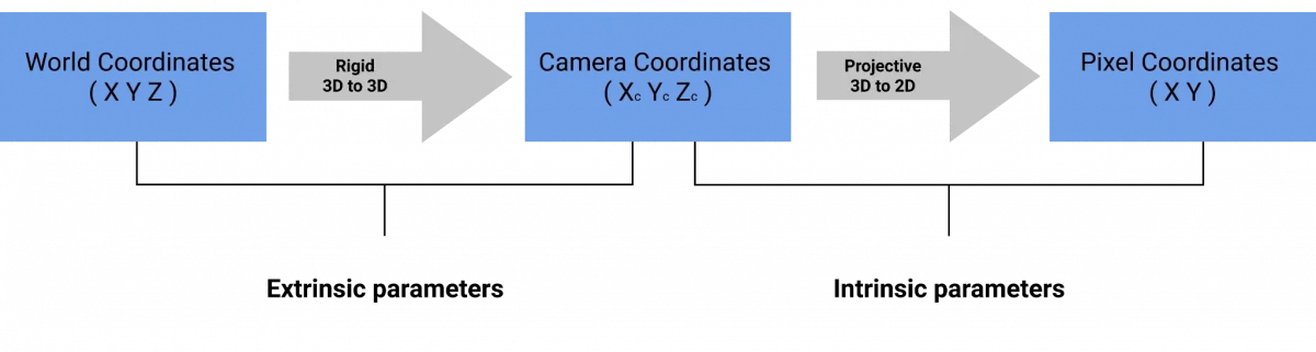
Extrinsic Calibration is the conversion from World Coordinates to Camera Coordinates. We're basically saying "Here's a point in 3D in a specific coordinate frame. What would be the coordinate of this point if we'd look from the camera frame?". A point in the world is rotated to the camera frame, and then translated to the camera position. The extrinsic parameters are called R (rotation matrix) and T (translation matrix).
Intrinsic Calibration is the conversion from Camera Coordinates to Pixel Coordinates. Once we have the point in 3D, we're using the intrinsic parameters of the camera to convert this 3D point into a Pixel. This is done using the focal length, which is a property of the camera that represents a distance between the lens and the image.
The intrinsic parameters is just a matrix called K, that includes the focal length and other internal parameters of the camera.
So:
- Extrinsics: R and T, World to Camera frame conversion matrices
- Intrinsics: K, Camera to Pixel conversion matrix
Next, let's see how it works with OpenCV.
Camera Calibration: Stereo Vision & OpenCV
Generally, we use a checkerboard and automatic algorithms to perform it. When we do it, we tell the algorithm that a point in the checkerboard (ex: 0,0,0) corresponds to a pixel in the image (ex: 545, 343).
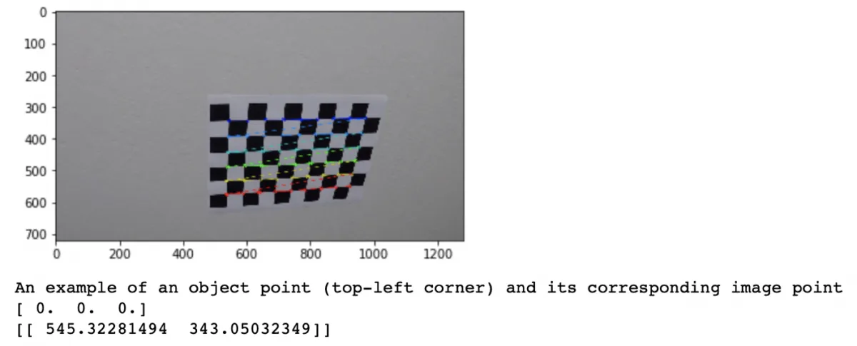
For that, we must take lots of images of the checkerboard with the camera, and after some images and some points, a calibration algorithm will determine a calibration matrix for the camera by minimizing a least square loss.
Generally, calibration is necessary to remove image distortion. Pinhole camera models include a distortion, the “GoPro Effect”. To get a rectified image, a calibration is necessary. A distortion can be radial or tangential. Calibration helps to undistort an image.
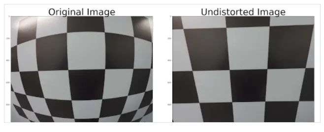
👉 At the end of the calibration process, you have two rectified images, with the parameters K, R, and T.
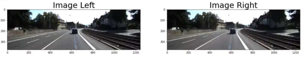
Let's see what this looks like on an autonomous driving example taken from the KITTI dataset, our 2 stereo images are rectified and give us this:
Let's see why we built these in Stereo:
Step 2 — How Epipolar Geometry leads to Visual Depth Estimation
When looking at a scene, our eyes can give us an understanding of the depth of each object. They triangulate the scene, and give us an idea of how far the object is (you can also do it with one eye, but this is only because your brain learned to extrapolate what your other eye would have seen).
Stereo Vision reproduces the same idea in a robotics way. We have two cameras aligned along the same y and z axis, and looking at the same thing. We call that a stereo setup.
What to do with 2 cameras?
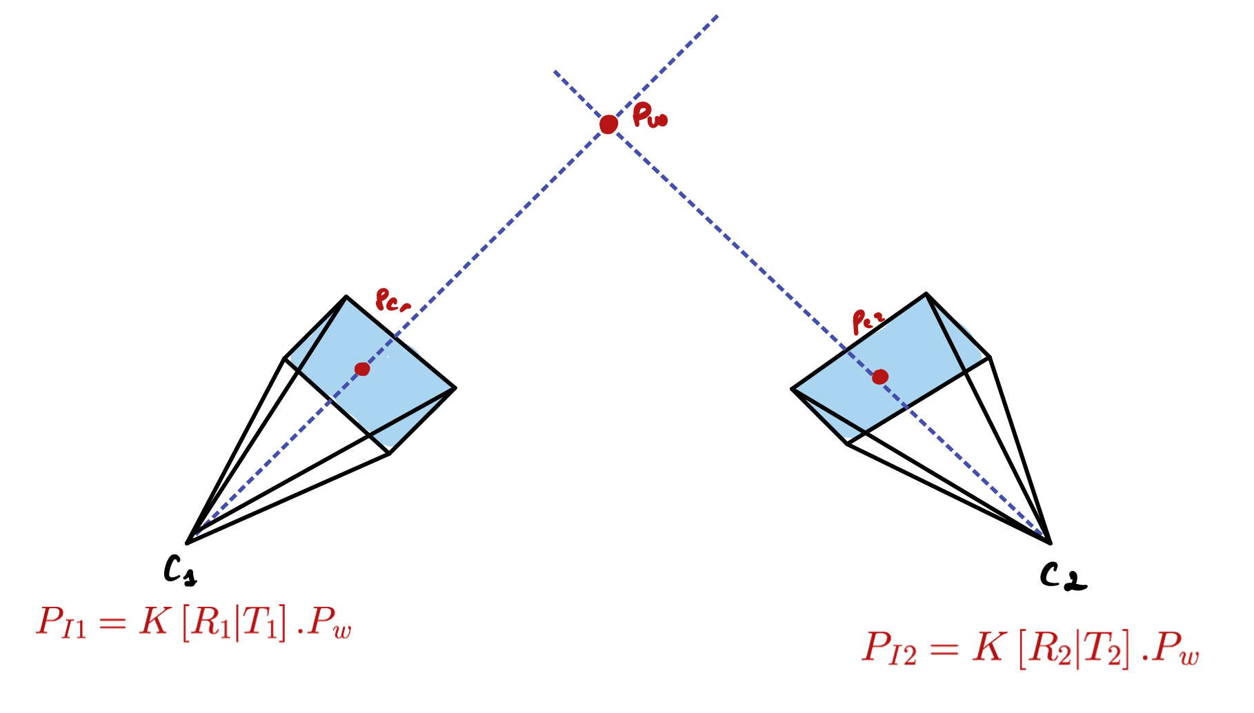
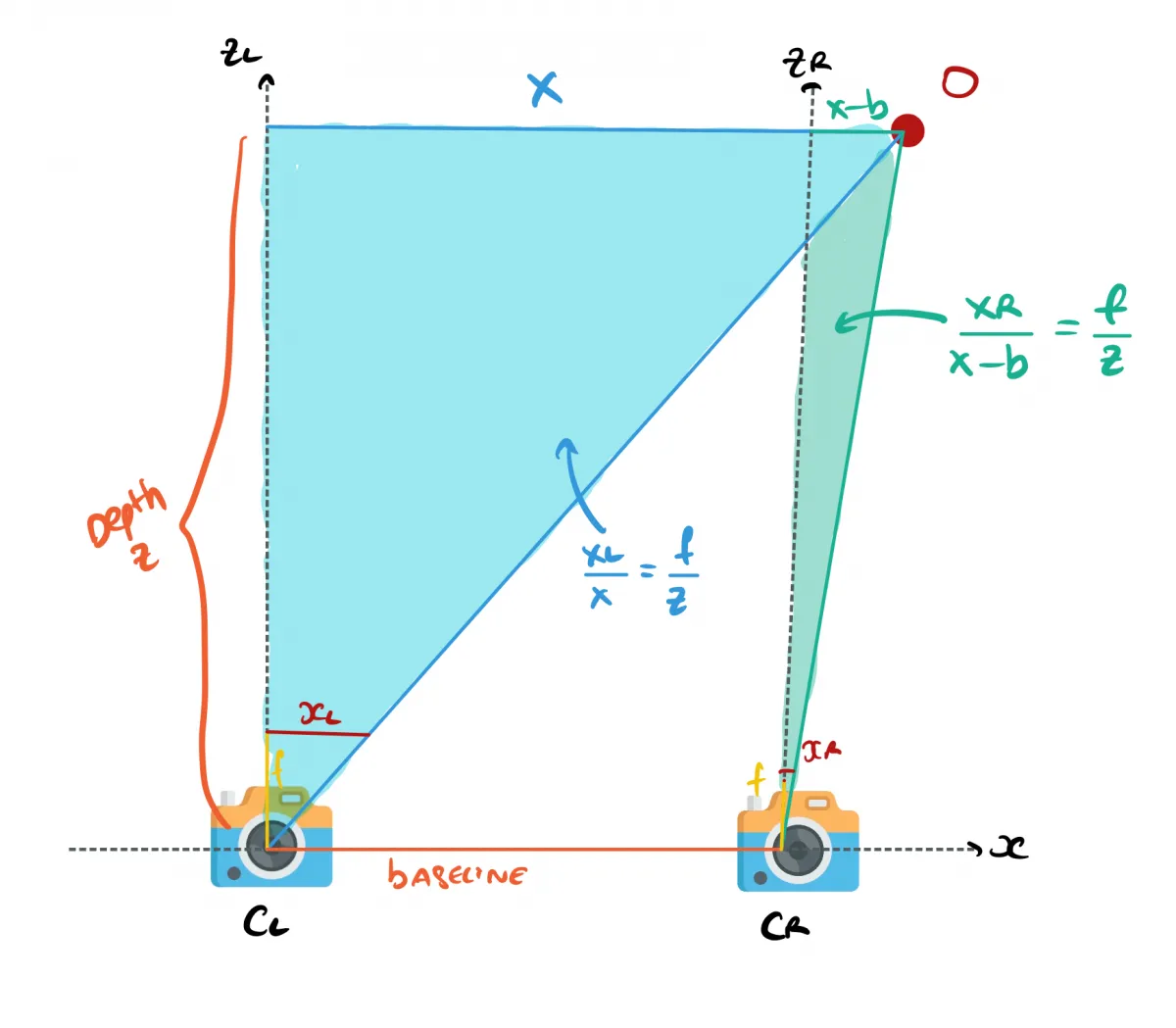
Take two cameras CL (camera left) and CR (camera right) looking at an obstacle O. If you start writing down some parameters, you'll quickly arrive to this image:
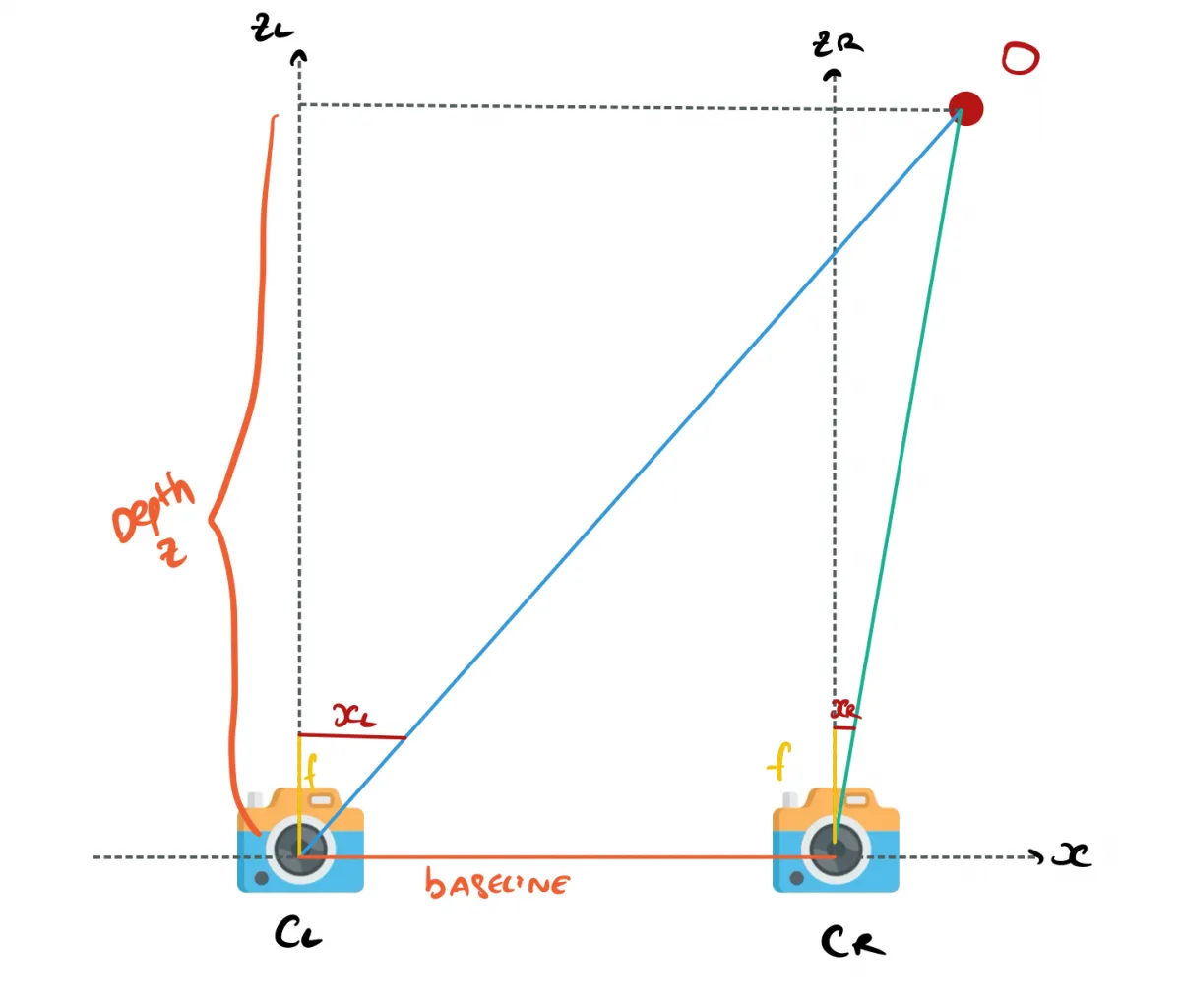
In this setup:
- X is the alignment axis, Y the height, Z the depth
- xL corresponds the point in the left camera image. xR is the same for the right image.
- b is the baseline, it’s the distance between the two cameras.
From there, you'll want to estimate the Z value, the distance to the obstacle O. How do you do that? You use similar triangles! Using geometry and similar triangles, you can recover formulas for XL and XR, and both of these formulas will involve Z.
From there, you can build 2 formulas for the left and right cameras:
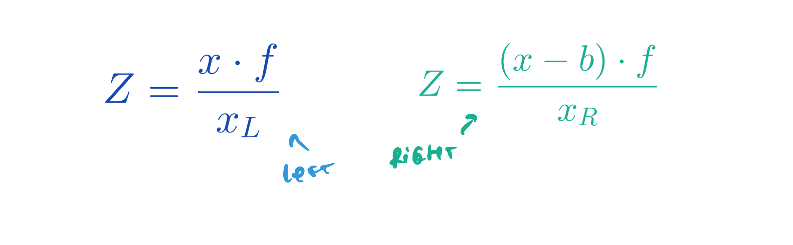
When we do the maths, we can quickly arrive to Z, and can even derive X and Y.
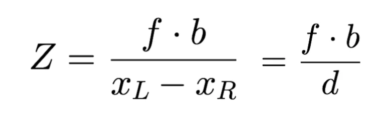
So, we understand that to build a Pseudo-LiDAR, we can use 2 cameras and similar triangles to potentially recover the distance of every pixel of an image. All we need is to understand what is d (xL - xR) in our formula above. And this is what's called Disparity Estimation.
Step 3 — Disparity Estimation from Stereo Images
First:
What is the Disparity?
The disparity represents the difference in pixels of the same point from 2 different angles.
For example, let's take an autonomous driving 3D object Detection example, where we see a car on the left side of the images.
Let's take a random point, the side mirror on the left image at pixel (300, 175). This same mirror is located at pixel 250 on the right image. So xL = 300 and xR = 250.
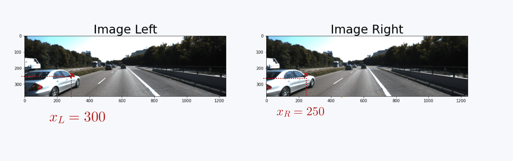
From there, we can compute the disparity (xL-xR), it's therefore 300-250 = 50 pixels.
Compute this for every pixel, and you get a disparity map! As you can see, close objects are lighter than far away objects that are represented in darker colors. We already have a sense of depth!
Stereo Matching & Epipolar Search
So how do you get the Disparity with a Computer? I showed you how a mirror was at Pixel 300 and 250, but how would a computer do it? Well, the concept of pattern recognition can be used, from example by computing specific features and finding them using a sliding window.
But before we see this, notice something with the mirrors, don't they strangely look "aligned" on the same height?
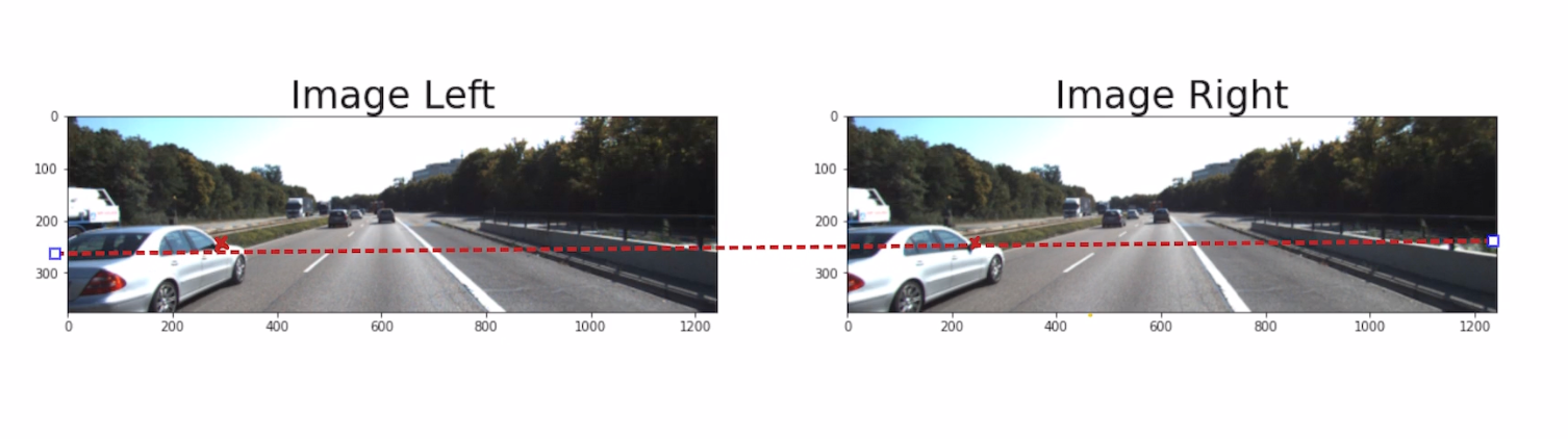
As in the example above, the mirror is on the same height because of the stereo calibration and rectification. We have a 1 dimensional search only. This is also because the cameras are aligned along the same axis. We call that axis the epipolar line.
Let's go back to stereo matching:
The correspondence problem, also known as epipolar search, can be done via traditional techniques (usually implemented in libraries like OpenCV). In these techniques, algorithms such as StereoBM or StereoSGBM find patterns in one image and then search for them in the corresponding pair.
Other techniques such as Deep Learning are now adopted these days, with the use of algorithms such as CRE-Stereo that was introduced at the CVPR 2022 (Computer Vision and Pattern Recognition) conference. This type of approach achieves impressive improvements compared to traditional pattern recognition, and is 100% based on Convolutional Neural Networks.
Now, given our two initial images, here's what we've got:
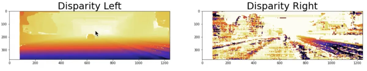
We now have a disparity map, but our goal is to build a depth map. It's going to be a 2D image as well, but unlike the disparity map where each pixel is encoded with a xL - xR distance value, each pixel will be encoded with a Z (depth) value.
Step 4 — How to build Depth Maps using 2 cameras?
So far:
- We got K, R, and T parameters (intrinsics and extrinsics) from calibration
- We built an Epipolar setup
- We used Stereo Correspondence to build a Disparity Map
What we can do now is apply the formula from Epipolar Setup:
In this formula, all values are known:
- We know the focal length 𝑓 obtained from the 𝐾 matrix (camera calibration)
- We know the baseline 𝑏, it's the distance between the 2 cameras in meters
- We know the disparity d
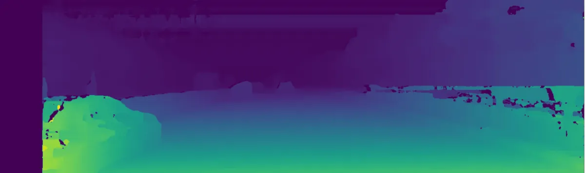
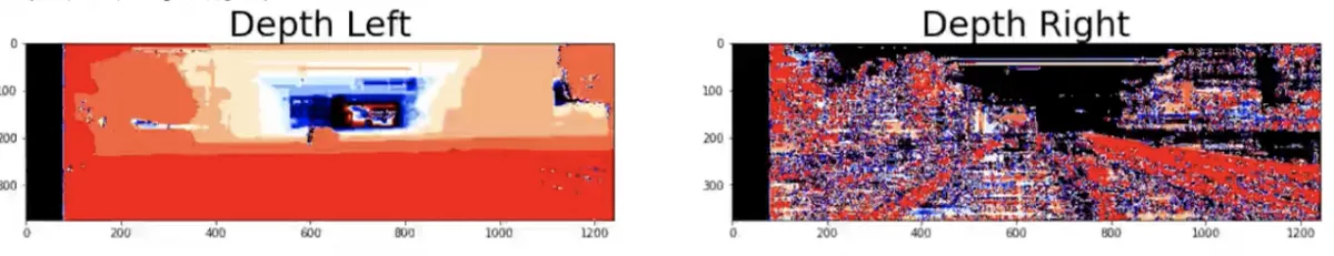
We do that depth estimation computation for each pixel, and we get 2 image based depth maps!
This brings us to the final part:
Step 5 — What to do with a Depth Map?
I would now like to talk about 2 main things you can do from this Depth Map:
- 3D Object Detection
- 3D Reconstruction
Let's start with camera based 3D Object Detection.
3D Object Detection
The idea is simple: 2D Object Detection + Depth Estimation = 3D Object Detection.
How do we do that? By combining our depth maps with 2D object detection algorithms such as YOLO. Such algorithms will return, for every obstacle, a bounding box with 4 numbers: [x1; y1; x2; y2]. These numbers represent the coordinates of the upper left point and the bottom right point of the box.
We can run this algorithm on the left image for example, and then use the left depth map.
Now, in that bounding box, we can take the closest point. We know it, because we know the distance of every single point of the image thanks to the depth map. The first point in the bounding box will be our distance to the obstacle.
Boum! We just built a 3D object detection system from 2 cameras alone! Thanks to stereo vision, we know not only the obstacles in the image, but also their distance to us! This obstacle is 22.75 meters away from us!
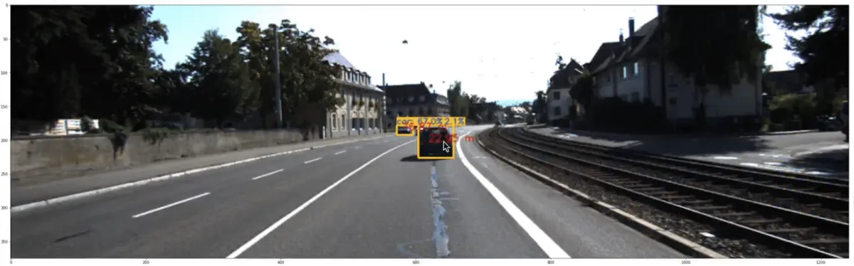
This process is pure visual depth estimation, we just use 2 cameras in a stereo setup, and the 5 steps above combined with object detection to get 3D object detection.
The other process is 3D Reconstruction:
3D Reconstruction: From Depth Map to Pseudo-LiDAR
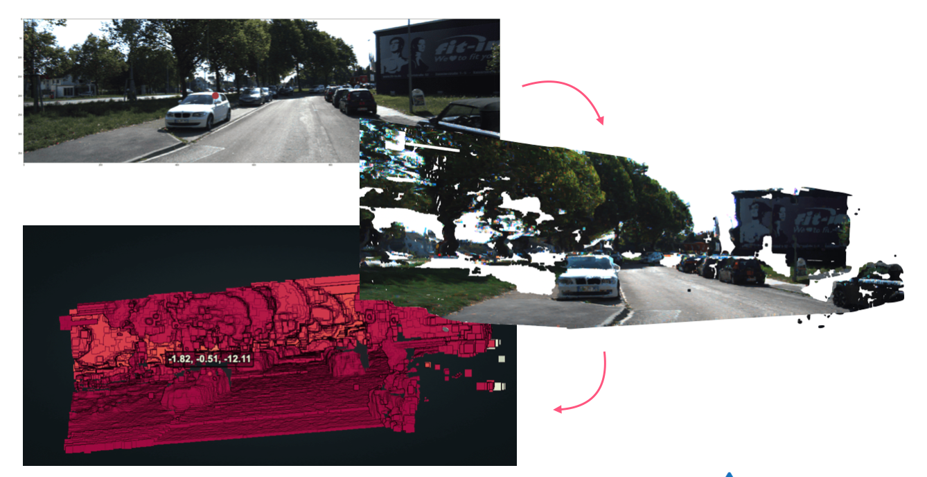
Getting 3D objects is great, but we can push it even further and "project" every single pixel of an image to the 3D space. That is called 3D Reconstruction, and this can completely build the Pseudo-LiDAR we are aiming for.
This process can be done using OpenCV and complex maths (involving perspective transform and other techniques). Here is what it looks like:
Of course, this is only 2-View Reconstruction, and if you want to, you can also add more cameras to build a complete 360° view.
Here is the result animated:
In the end, you should be able to get a clear Pseudo-LiDAR from just two cameras. This can then be the base for LiDAR based 3D Object Detection algorithms, such as PointPillars, VoxelNet, PV-RCNN, etc... These are algorithms usually reserves for LiDAR Point Clouds, but that could operate on reconstructed images as well (if the first solution isn't right for you).
Conclusion & Summary: How to build a Pseudo-LiDAR
So let's summarize what we learned on the Pseudo-LiDAR:
- In a Pseudo-LiDAR, our goal is to replace a LiDAR signal by pixels. When using cameras, we don't have to go through the hassle of purchasing expensive lidar technology. In autonomous driving, this approach is used by Tesla, but also Comma.ai or Mobileye.
To built a Pseudo-LiDAR, we use 5 steps:
- Camera Calibration — Intrinsic & Extrinsic Parameters are obtained through camera calibration
- Epipolar Geometry — We setup a stereo vision system and collect our values for baseline, focal length, etc...
- Disparity Estimation — We build a disparity map using disparity search
- Depth Mapping — We turn the disparity into a depth map using the camera parameters
- 3D Reconstruction — We project every pixel in the 3D space and reconstruct a point cloud.
- If we want to do 3D object detection, we can do it via the camera or the LiDAR. We either combine 2D Object Detection with Depth Estimation, or we combine 3D reconstruction with LiDAR-based 3D object detection algorithms such as PointPillars or PointRCNN.
So what is the accuracy of such approach? In August 2020, Tesla, claimed that they reached LiDAR accuracy using just cameras. A few years later, their system still uses cameras only, and keep reducing the cost of their system. Curious about the approach, I wrote a blog post where I detail an experimentation comparing a Pseudo-LiDAR with a Sensor Fusion system. You can read it here.
As a Computer Vision Engineer, I would like to finish this article by mentioning an important point. None of this could be build if you have no ideas how cameras work, and are just focusing on processing images.
In the field, we don't just do image processing, but we also do camera processing. If all you do is based on image, you miss the part that involves the understanding of the camera, the retrieval of parameters, the projections from one space to another, and you even lose access to some applications, such as visual depth estimation, video processing, or Sensor Fusion.
Finally, if you're not in my daily emails yet, I highly recommend you join them. It's where I speak more in depth about what engineers need to learn, and how they can learn these algorithms. We talk about building a Pseudo-LiDAR, but we also talk about LiDARs, Video Processing, HydraNets, Sensor Fusion, and much more.
I also happen to have a course on Stereo Vision & 3D Computer Vision. It covers everything from basic stereo geometry to advanced 3D Object Detection and 3D Reconstruction; and it even has a DLC just on 3D Reconstruction. It's called MASTER STEREO VISION, you should check it out.