How Visual Inertial Odometry (VIO) Works
Sherlock Holmes was seated on a chair, blindfolded. Suddenly, someone took off his hood, to reveal a grand office where a man in his late 60s, Sir Thomas, is sitting in front of him.
"Mr. Holmes" started the man. "Apologies for summoning you like this. I'm sure it's quite a mystery as to where you are, and who I am." He started proudly.
Holmes, played by Robert Downey Jr, took a second of silence, before starting: "As to where I am -- I was, admittedly, lost for a moment between Charing Cross and Holborn. But I was saved by the bread shop on Saffron Hill, the only bakers to use a certain French glaze on their loaves. After that, the carriage forked left, then right, a bump over the Fleet conduit -- need I go on?"
In shock, his kidnapper then listened to Sherlock giving the rest of the speech, up to the punchline:
One of the best skill Sherlock Holmes had in this scene is his ability to – even blindfolded – understand exactly where he is, and this by counting how long he drives to a place, identifying when he turns, and recognizing specific cues, such as the bakery's smell.
This is, my dear reader, exactly the principle of Visual Odometry in autonomous driving, and in this article, we're going to talk about how robots use cameras (visual = camera based) to recognize where they are, and how they're moving in a 3D scene. We'll see traditional as well as new, Deep Learning based approaches.
So let's begin, we'll cover 3 points:
- Visual Odometry: the idea of estimating your pose based on what you see
- Inertial Odometry: the idea of estimating your pose based on how you move
- Visual Inertial Odometry: the fusion of the two
Visual Odometry
The first idea is "visual odometry", and this means... What if sherlock was not blindfolded? What if he was somewhere in an unknown place, with no map (and this will be our example all along the article), and was suddenly driven somewhere else??
Sherlock Holmes would use his eyes to recognize some key places, so he'd recognize a street where he turned, or he would see a bakery, a specific sign, and anything like this. In SLAM language, this is called a landmark. The problem is, in Computer Vision, you're not really going to detect bakeries and stuff like this.
Instead, you're going to use Visual Features. Visual Features are a key component, and I have an entire article on it, plus another one in the context of Visual SLAM. The idea of estimating your pose using Features goes like this:
- Run Feature Detection And Tracking
- Find Rotation and Translation matrices
Run Feature Detection And Tracking
To go really quick on it, because I already wrote about it (links above):
We detect features (pure pattern recognition of corners, edges, gradients, ...) and then match them from frame to frame. Algorithms like SURF, SIFT, BRISK, AKAZE, etc... are used for the detection and encoding, and others like Brute Force or FLANN can be used for feature matching. This gives a result like this:
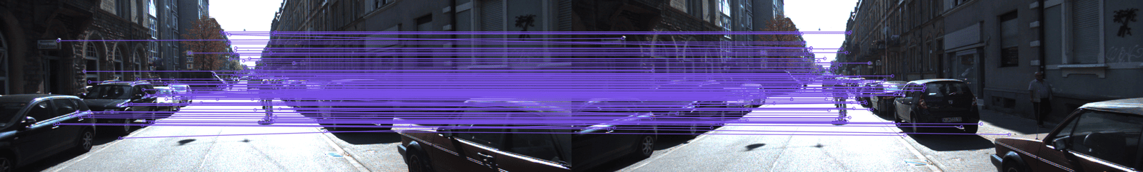
Okay, so we know how our features moved, then what?
Find Rotation and Translation matrices
From the features matched, we'll want to extract the camera motion, via some rotations and translation matrices. This is a popular 3D Reconstruction concept known as Structure From Motion(Sfm), and the idea is to use Computer Vision principles, such as the Fundamental and Essential Matrices; or the 8-Point Algorithm with RANSAC to recover R and T.
What are R and T? They're the Rotation (R) — a 3x3 matrix, and Translation (T) — a 3x1 vector, needed to go from the first set of features to the second. In theory, algorithms like the 8-Point algorithm use Singular Value Decomposition to figure out the Fundamental Matrix from 8 tracked features. In practice, we can use some OpenCV function to recover the position from the matched features:
p1 = #compute the features
p2 = #compute the features
K = #intrinsic matrix

# 1) Find the Essential Matrix E
E, mask = cv2.findEssentialMat(p1, p2, K, cv2.RANSAC, 0.999, 1.0);

# 2) Recover the rotation R and translation T
points, R, t, mask = cv2.recoverPose(E, p1, p2)
And you can even reconstruct entire scenes just using this. The principles are well detailed in my 3D Reconstruction DLC (an advanced module only for engineers already in my Stereo Vision course).
So this is the idea of Visual Odometry, we compute features, track them, and then recover the pose.
Inertial Odometry
The other type of Odometry is Inertial.
Let's go back to Sherlock. Imagine this time, he IS blindfolded, but he's walking, or let's say he knows exactly how fast the car that kidnapped him drives? Now, he can measure his travelled distance. If he walked 20 steps forward, then turned right, then took another 20 steps, he knows where he is.
This is "Inertial" Odometry, and this because you're often using one or more Inertial Measurement Units (IMU) to compute it. An IMU is going to use gyroscopes, magnetometers (measuring earth magnetic values), and accelerometers to compute how much you moved, how fast you're going, and how you're oriented. You can learn more about IMU through this Youtube video.
An example? Let's watch it on the KITTI Dataset here:
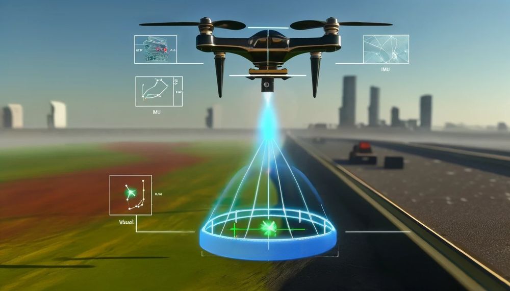
So what is Visual Inertial Odometry? The fusion of the two?
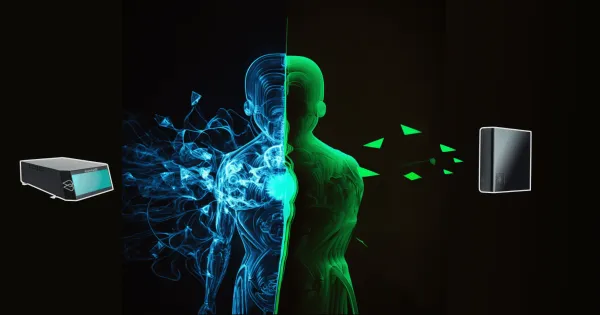
Yes! Exactly! And this will be our 3rd part (before seeing some examples). In VIO, we fuse what we learned from the visual features with what we learned from the IMU to achieve accurate state estimation. And how do we do this? How do we estimate the state of something by fusing two outputs? Anyone? Can someone plea—
"An Extended Kalman Filter!" yells a reader in the background.
Right! An Extended Kalman Filter! This is the main algorithm we'll use to combine the output from IMU with the output from Visual Odometry. How? Let's take a look:
Filtering Techniques for Visual Inertial Odometry
Well, the principle is what I call "sequential fusion", or sequential sensor fusion, because it happens in sequences:
- You get data from Sensor A (or algorithm A), and run Predict
- You get data from Sensor B (or algorithm B), and run Update.
And you do this in a loop, in a predict/update cycle, which is what a Kalman Filter does. I won't explain what a Kalman Filter is, you may check my Sensor Fusion post for this.
We said an EKF is the solution, but it's not the only solution. In fact, many algorithms today use another technique based on graph-SLAM: optimization.
Optimization Techniques for VIO
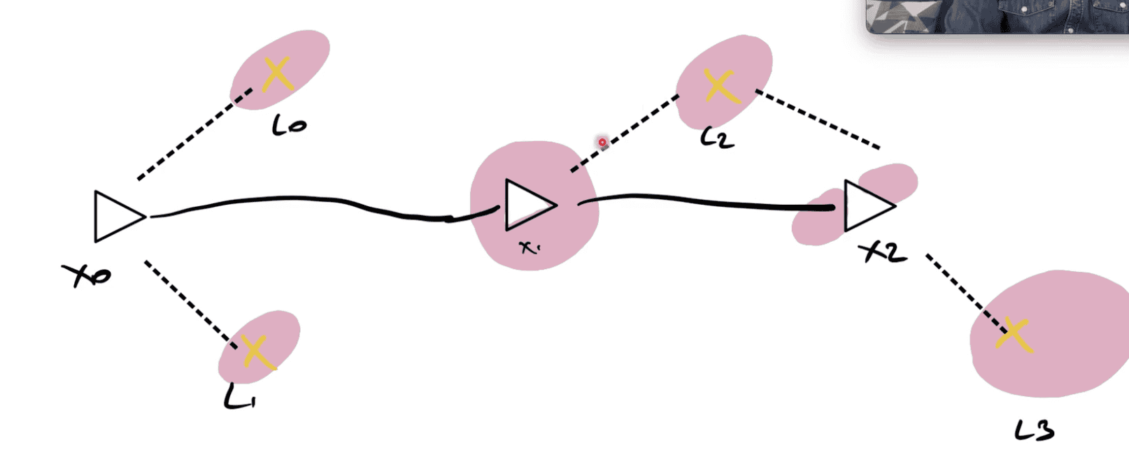
The second set is optimization techniques, and here, we're going to minimize a cost function that contains all the information. It's similar to Graph SLAM techniques, where we try to incorporate everything and have the minimal cost possible. Didn't get it? Me neither, let's see what I mean:
Imagine IMU says "we moved 2 meters" and camera says "we moved 2.5". Who is correct? In a Kalman Filter, it's (almost) an easy choice. We would do a Predict/Update cycle, add "weights" or covariances to each measurement, and have an answer somewhere in the middle. But if you're using optimization techniques, you don't do this.
Instead, you solve a Least Square Problem. This is often called non-linear optimization, and you usually refer to algorithms such as Levenberg-Marquardt or Gauss-Newton for this. This 'optimization' is about minimizing a cost function.
We want to satisfy every measurement. So if we're building a map, and try to hold uncertainties and assumptions for every possible landmark.
Alright, I won't really go further here, because it would require an entire book, but the gist is: we minimize a cost function.
Now let's see some examples.
Example #1: MSCKF (Multi-State Constraint Kalman Filter)
The process behind the MSCKF (multi-state constraint kalman filter) algorithm is shown here:
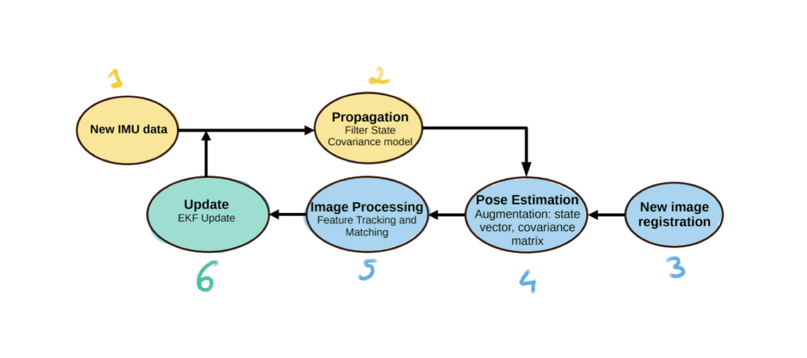
Here are the steps involved:
- New IMU Data: Gotta start somewhere, and new inertial measurements are what begin our cycle.
- Propagation (EKF Predict): We immediately run a Kalman Filter 'Predict' step. Using the new IMU data, the state and covariance are propagated forward in time based on the IMU model.
- New Image Registration: Right after Predict, we add the new image.
- Pose Estimation Augmentation: This step augments the state vector and the covariance matrix with information derived from the new camera images. Basically, we prepare our Kalman Filter for an "update".
- Image Processing (Feature Tracking and Matching): This is where features are extracted from the images, tracked, and matched. Pure Visual Odometry.
- Update (EKF Update): Finally, we update the state based on the features tracked! The filter incorporates the visual information to correct the state estimate and reduce uncertainty, improving the accuracy of the pose estimation.
Because it's a Kalman Filter, we'll do that in a loop. Step 7 is to incorporate a new IMU measurement, and so on...
So, to reduce it even further it's:
Inertial Odometry >>> Predict >>> Visual Odometry >>> Update >>> Repeat.
Example #2: VINS-MONO
Ever saw a LinkedIn post with 300+ likes showing a Visual Odometry algorithm called VINS-MONO? I have ✋🏽. The principle behind this VIO algorithm (Monocular Visual Inertial System = Mono VINS) is really cool, let's see:
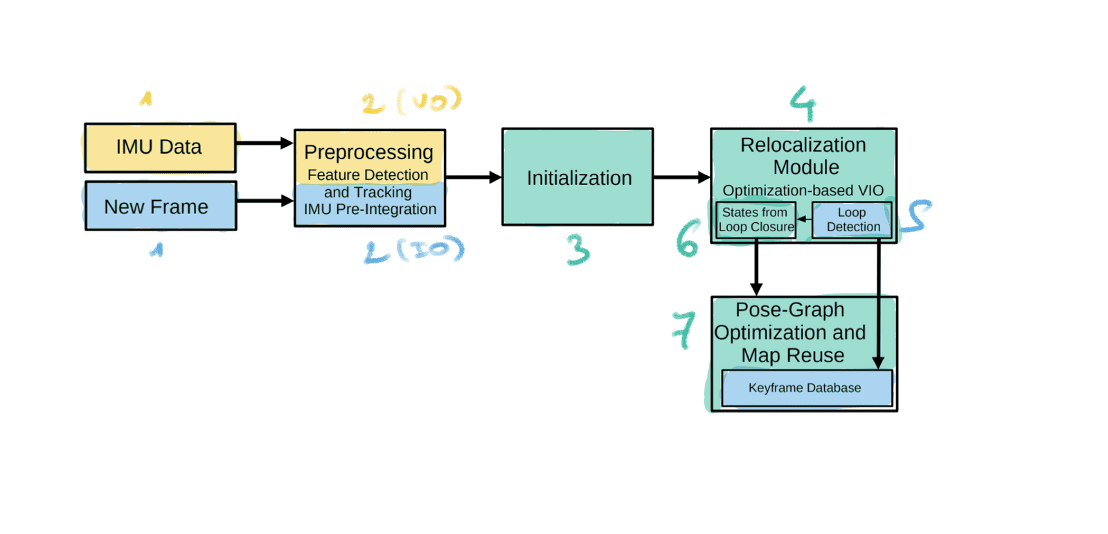
- New IMU Data & Frame: This time, we process them in parallel.
- Preprocessing: This step is both Visual Odometry (for the camera) and Inertial Odometry (for the IMU).
- Initialization: This step is where we initialize our "graph" and put the values inside of it based on our two measurements. This step is already a fusion of the two values into the common map.
- Relocalization: Finally, this step is an "optimization" step based on Loop Closure Detection. I wouldn't call this part pure odometry, it's already in the mapping part with SLAM. I have an entire article on Loop Closure here.
- Pose-Graph Optimization: Same idea, here we're already out of Visual Inertial Odometry, it's really the global optimization after doing several laps of a city. However, this step also corrects the position, so it's a bit part of odometry too.
Are there just these two families?
Usually, yes. We could probably find a "Deep Learning" family, and explore sub-families of each like Graph-SLAM but in anything SLAM, we usually refer to these techniques: we either solve an optimization problem, or we use a Kalman Filter. If we look at the mini-graph, it would be like this:
Okay, recap time!
Summary
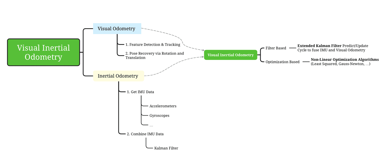
- Visual Inertial Odometry is the idea of fusing Visual Odometry (from the camera) with Inertial Odometry (from an IMU: Inertial Measurement Unit). Combining both can have great benefits, as for every sensor fusion algorithm.
- Visual Odometry usually happens by detecting features, matching them from frame to frame, and then recovering the motion via Rotation & Translation matrices.
- Inertial Odometry is the idea of fusing all the data from an IMU (gyroscope, accelerometers, ...) to get an estimate of how we moved over time. We can recover the 3D pose, acceleration, velocity, orientation, and more...
- To do VIO, we can use a Kalman Filter based approach. We would typically use an Extended Kalman Filter, and then fuse IMU and Visual Features sequentially with a Precict/Update cycle. An algorithm like MSCKF does it.
- We could also use non-linear Optimization algorithms, such as VINS-MONO, to optimize the estimate of the landmarks and our position via a cost function minimization.
Awesome, you've been through the article. 🙌
Conclusion
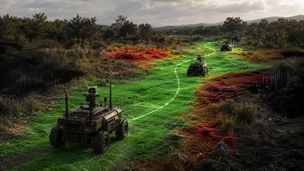
Visual Inertial Odometry (VIO) is an idea that is really popular in the SLAM space, because it's the only viable alternative to the total absence of GPS. If you have no GPS, then you HAVE to have an IMU and do the VIO processing. It's also a really good alternative to LiDAR Odometry, in situations where... well, where you don't have a LiDAR.
Today, VIO systems can work both on self-driving cars, or in an aerial robot (yeah a drone), or outdoor ground vehicles (for example for military applications), or in really most intelligent robots equipped with an IMU and one or more cameras.
We saw an example with one IMU and a single camera, but we can have a different sensor data setup. Some algorithms also work in Stereo, and thus leverage 3D Computer Vision; and we could also have multiple IMUs.
If you are to learn about SLAM, I would probably NOT begin with a topic like Visual Inertial Odometry. It's actually quite advanced, but you could fit it somewhere in your curriculum after learning about SLAM and Odometry in general.
Next Steps
- As an introduction to this article (should have mentioned it earlier, oops), you could read my article on the The 6 Components of a Visual SLAM Algorithm.
- You can also read my other Localization articles, such as Robot Mapping, Loop Closure, or my SLAM Roadmap.
- I have a course on SLAM. It's most of the year closed, by I open sessions every once in a while. If you're interested, you can read the page here and join the waitlist here.
Finally: